

Hedge cutter and mower flails, plus the heavy rotors employed in forestry mulchers, run more efficiently and safely when correctly balanced. Here we look at the mobile dynamic balancing techniques employed in Europe by Croation company Vibroteh to keep even the heaviest of rotors running smoothly.
KEEPING IT BRIEF
- Vibroteh dynamically balances rotors in two planes. This can entail fitting weights at each end of a rotor shaft.
- Balancing is carried out with the rotor mounted in the machine, complete with the flails or teeth.
- The aim is to achieve a level of balance compliant with DIN ISO 21940-11 and to quality grade G16. The latter covers the key rotating parts used in agricultural equipment to include flails and mulchers.
Flails and heavy-duty forestry mulchers are exposed to enormous centrifugal forces. The heavier the unit the greater the mass that needs to be kept in balance. The rotors in a forestry mulched can weigh several hundred kilos and run at speeds of over 1,000rpm to achieve the desired results. If a rotor runs out of balance, the excess vibration will not just make the machine unpleasant to use it will also risk expensive damage.
Hrvoje Senecovic´ and Antonio Antunovic´, from rotor balancing specialists Vibroteh, travel through Germany, Austria and Switzerland with mobile, certified balancing equipment to balance shafts in situ. The aim is to keep contractors working without the need to take expensive equipment off-site for attention.
To see how the job is done, we visited the duo in Germany where they had been called in to work on kit operated by mulching and reforestation contractors Albert. Working on a contract to clear power line corridors, Albert were at the time operating a broad range of forestry mulchers, all receiving routine attention to keep them running ‘in balance’.
What is imbalance?
Imbalance can be summarised as the mass of a shaft not being evenly distributed around its axis. When the main axis of inertia doesn’t coincide with the axis of rotation, it causes vibrations when rotating. The quality grades described in DIN ISO 21940-11 classify how much vibration is permissible in rotating parts, with quality grade G16 applicable to agricultural kit to include mulchers. The set limits will depend upon the rotor mass and its speed of rotation. This will mean a heavy rotor can still be within tolerance when one that is lighter at the same rotational speed will fall outside it.
Actual unbalance is specified in gramme-millimetres (gmm). This is determined by measuring the unbalanced mass and multiplying it by the distance from the shaft’s central axis.
Causes and consequential damage
As anyone who has worked with a flail or mulcher will know, balance can be upset if the rotor shaft is heavily soiled. Equally, it is established that replacing a single damaged flail or tooth can cause unbalance as the weight of the new part differs from all other flails or teeth on the rotor. There is also damage that can be caused by hitting foreign objects causing shaft deformation or bearing play.
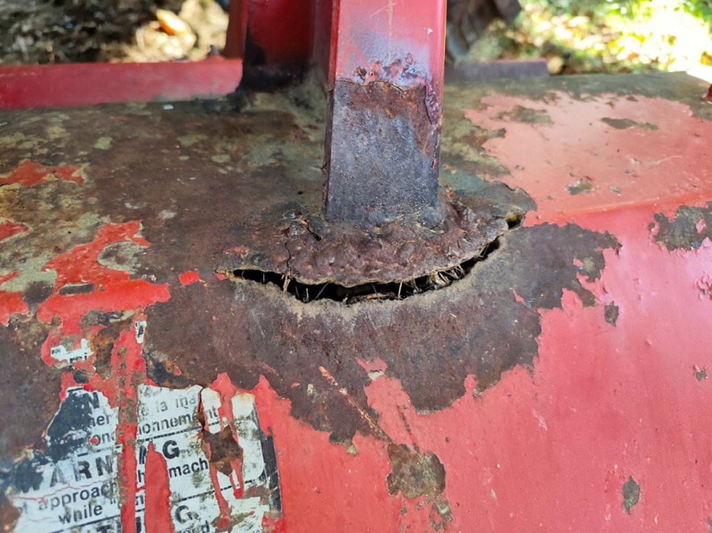
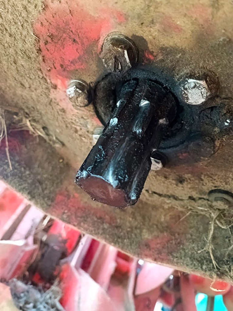
Whatever the cause, the stronger the vibration, the greater the risk of consequential damage. Typical signs of excess vibration can include cracks and fractures in the rotor housing, but the entire driveline can also be affected, to include the tractor.
Balancing shafts and rotors in situ, with flails or teeth in place, saves time removing them with the added advantage taking the wear of existing flails or teeth into account. Further, the equipment can be checked as it is put back to work.
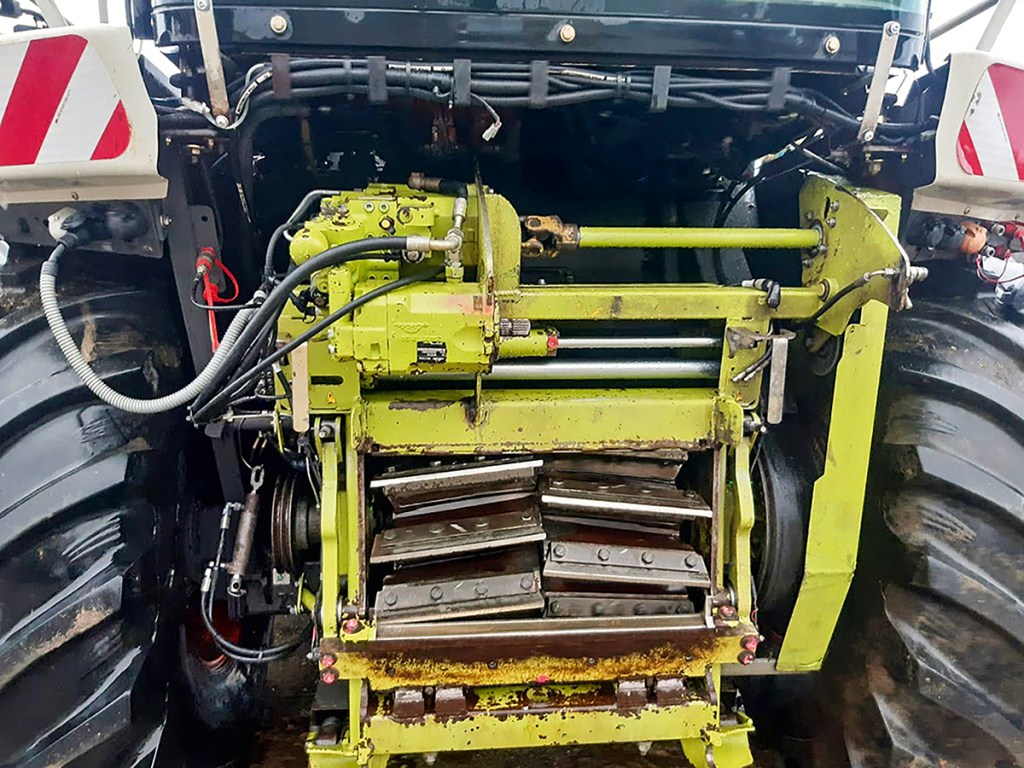
Dynamic balancing
With dynamic balancing, unbalance is determined not just at one point perpendicular to the shaft axis, but also axially along the shaft length. By attaching vibration sensors to the mulcher housing, near the rotor bearing at either end of machine, the rotor can be run up, with its speed of rotation also measured. This is done by gluing a reflective strip to a drive pulley, with a laser pick-up measuring the rpm.
The vibration and speed readings are simultaneously processed by software that calculates the unbalance. If weight needs to be added, the software will show both its mass and where it should be fitted to correct the problem. Several runs are typically needed (see following pages).
Although it is balancing mulcher rotors that is the main workload for Vibroteh, the company’s engineers also balance forager, combine and woodchipper drums. “Anything that spins is within our remit. A shaft or rotor operating at speeds of 300rpm plus will benefit from balanced running,” says Hrvoje Senecovic´
Costs
A big advantage of in situ balancing is that no shaft or tool needs to be removed, with balancing carried out with the machine in operating condition. Balancing results in a smoother running machine which makes it better to use and reduces the chances of consequential damage. Vibroteh prices its service by rotor length. Dependent upon machine type, the company will charge between €400 and €800 (plus travel costs) to balance a 2.0m rotor.
Alexander Bertling
For more up-to-date farming news click here and subscribe now to profi and save.
STEP BY STEP GUIDE
VISUAL INSPECTION
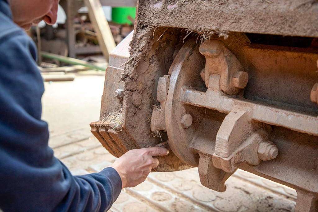
Step one is a visual inspection of the rotor, checking for heavy contamination with dirt and foreign objects such as fencing wire. The rotor shaft is also checked for missing flails or teeth. An initial inspection of the bearings is also made, any play having an impact upon the balancing result.
SETTING UP THE MEASURING EQUIPMENT
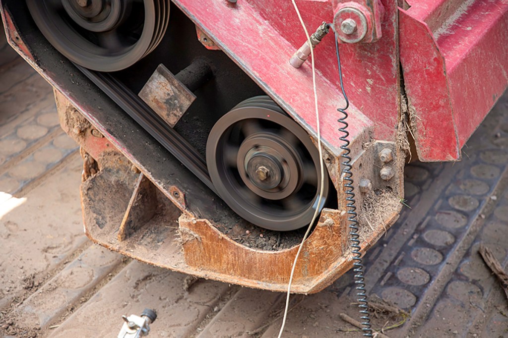
The vibration sensors are attached to the housing and near the bearings on either side of the attachment. Pulley and belt covers are removed as necessary to enable the laser sensor to measure the rotational speed.
FINAL MEASUREMENTS
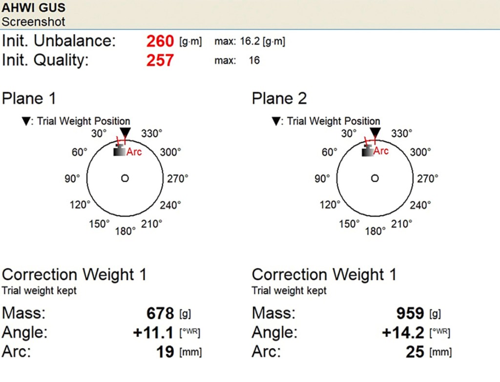
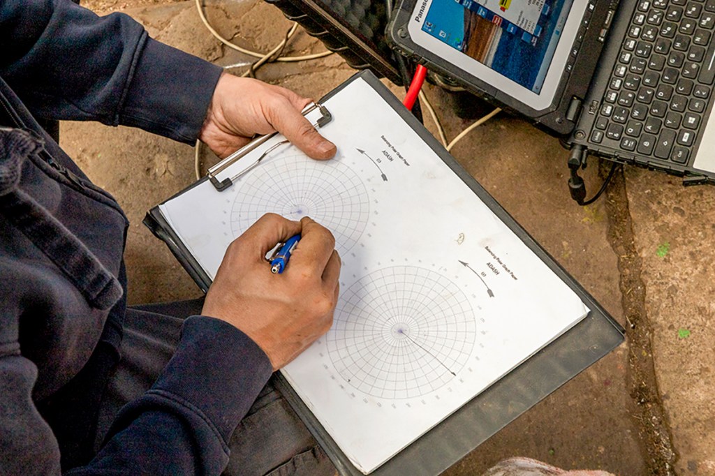
After carrying out at least two measurements, the software will outline recommendations where any weights are needed to be added and their mass. The weights need to be positioned so they don’t foul the flails or block the fixings. Clearly, the software can only make recommendations, with the recommended mass distributed on the shaft to allow for future servicing needs. This can mean four to five runs will be needed to ensure the rotor runs smoothly once weight has been added. The balancing procedure is documented manually to ensure there is a written record of the work carried out.
INITIAL MEASUREMENTS AND ATTACHING THE TEST WEIGHTS
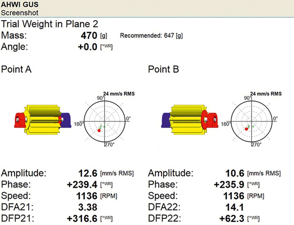
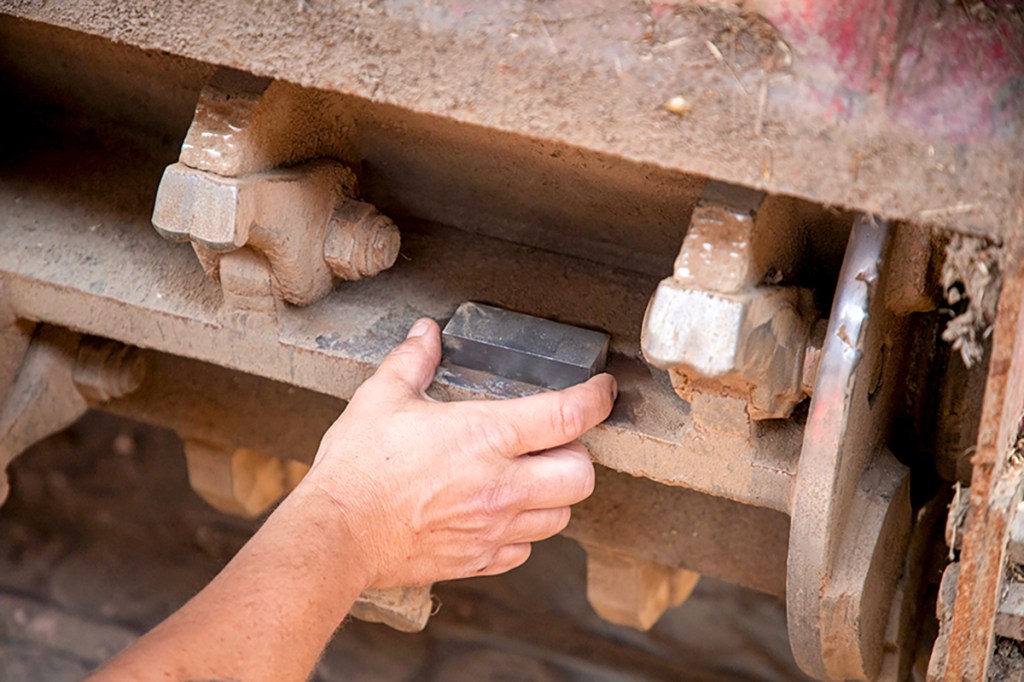
An initial measurement is taken to determine the current condition of the rotor. Trial weights of perhaps 300g are attached to left and right end of the rotor with another measurement taken, with red dots giving a visual indication of the degree of unbalance. The aim is to get the red dots within the diagram as close as possible to the centre at which point the unbalance has been eliminated.
WELDING WEIGHTS ALL ROUND

Once the balancing result is satisfactory, added weights are welded in place. They are positioned so they do not get in the way of any fastener used to secure a tooth or flail in place.